


Hello, this is "Narrow Gauge Shop".
-

Narrow Gauge Shop in Japan, with a passion for handmade products!!
This article is the second part of our turnout construction guide — the Soldering Section — following our Rail Construction Section, where we explained how to build compact-radius turnouts not available in commercial products.
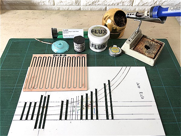
Tools and materials are explained in the Rail Construction Section, so please check that out first if you haven't already.
https://youtu.be/al9CcdhI7bw
・…━… 目次 …━…・‥
How to Build a Turnout [Soldering Section]
Once the track parts are completed, it’s time to move on to the soldering process.
Before we begin, let’s review the key points for clean soldering.
Tips for Clean Soldering
- Keep the soldering tip clean at all times!
- Heat the area thoroughly before applying solder!
- Don’t use too much flux!
- Use a small amount of solder at a time! Add more only if needed.
- Do not move the tip until the solder has fully melted and flowed!
Soldering Sequence to Avoid Mistakes
We’ve built turnouts of various radii and gauges over the years. The “Soldering Sequence to Avoid Mistakes” is based on that hands-on experience.
The order of soldering is crucial when building turnouts.
You can reduce the risk of mistakes and the need for rework by carefully choosing where to begin.
There’s no absolute right answer, but this is a proven method to build turnouts with high accuracy and smooth operation.
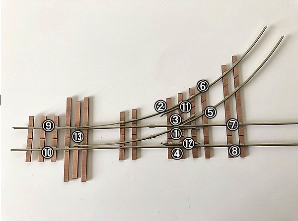
Recommended Soldering Sequence
- Curved Closure Rail + Wing Rail ... ①
- Stock Rail (Branch Line) ... ②
- Straight Closure Rail + Wing Rail ... ③
- Stock Rail (Main Line) ... ④
- Frog Rail (Branch Line) ... ⑤
- Stock Rail (Branch Line) ... ⑥
- Frog Rail (Main Line) ... ⑦
- Stock Rail (Main Line) ... ⑧
- Stock Rail (Branch Line) ... ⑨
- Stock Rail (Main Line) ... ⑩
- Guard Rail (Branch Line) ... ⑪
- Guard Rail (Main Line) ... ⑫
- Switch Point Rail (Tongue Rail) ... ⑬
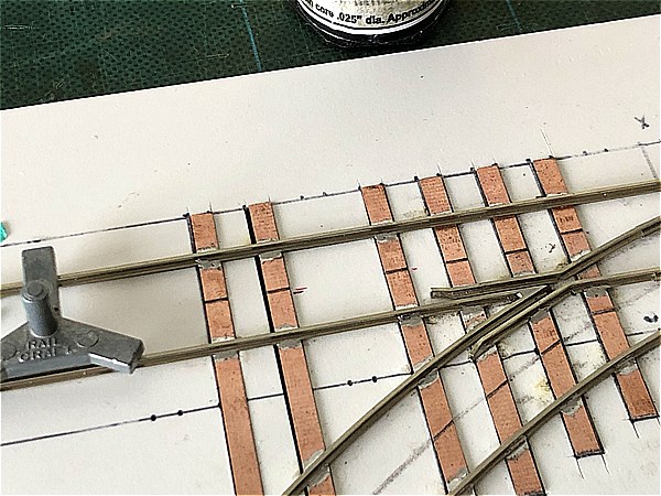
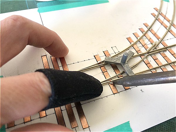
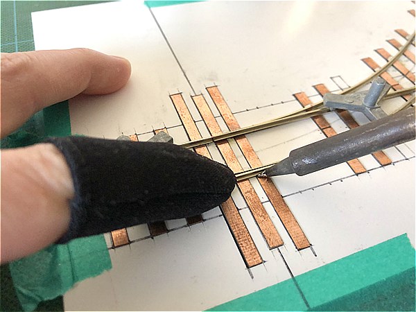
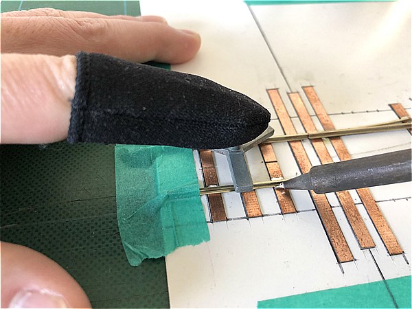
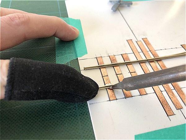
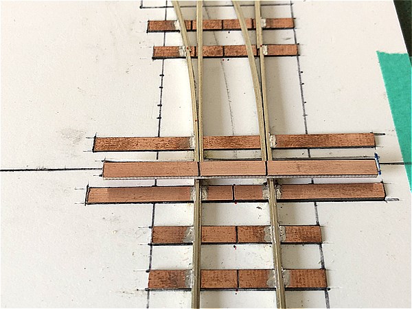
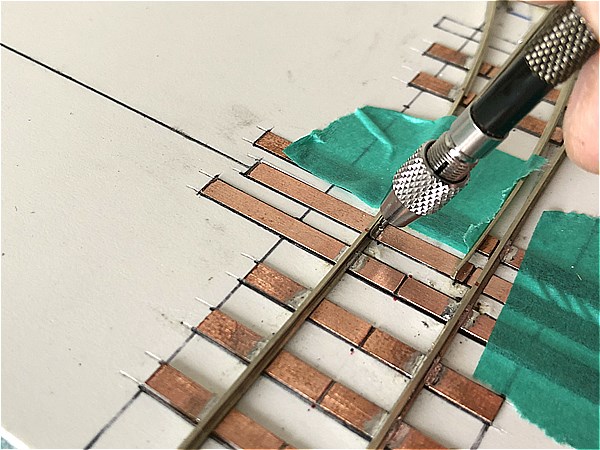
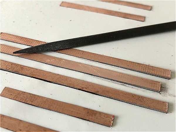
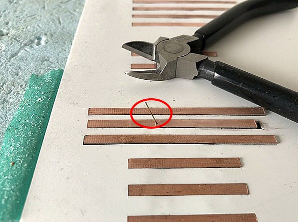
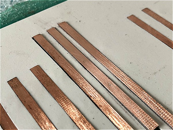
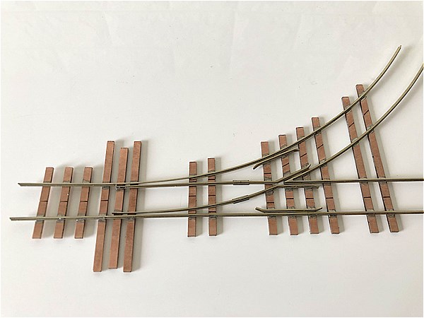
Cutting the PC Board Ties and Adding Gaps
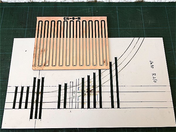
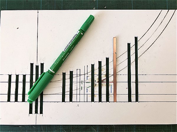
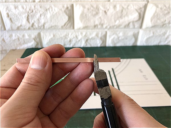
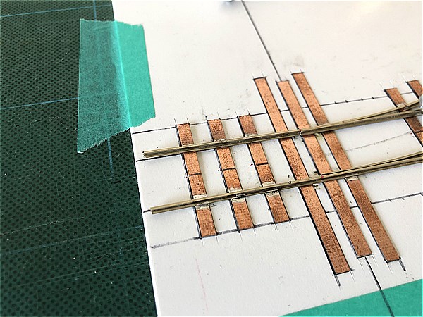
Cut the PC board ties according to the baseboard (jig) template.
*The position and number of PC board ties don’t have to match the images exactly — adjust as needed.
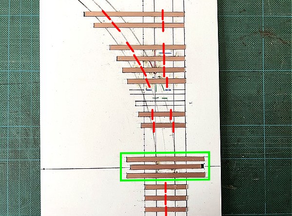
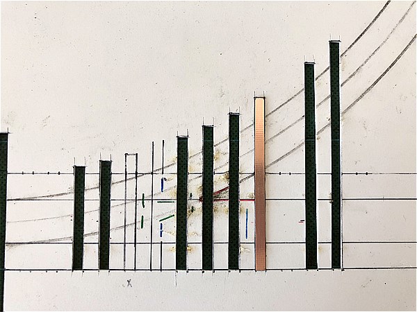
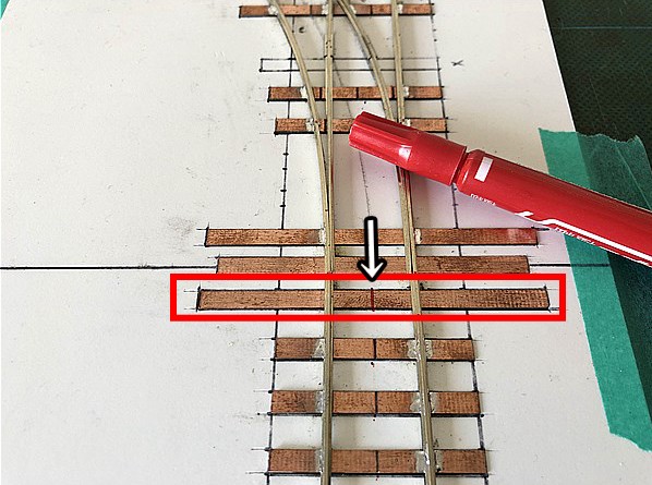
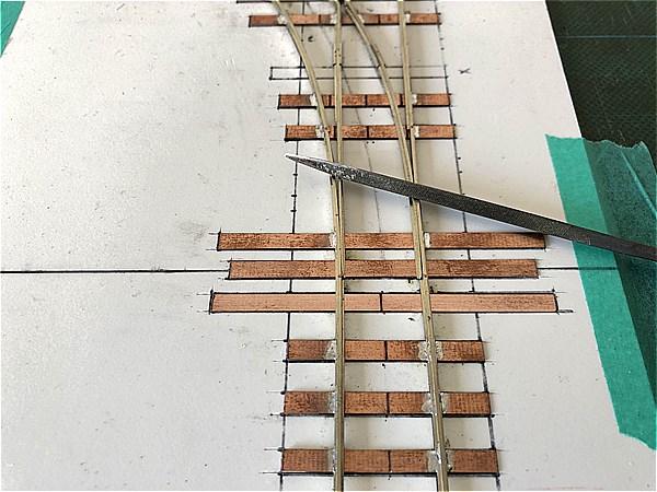
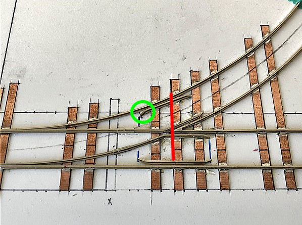
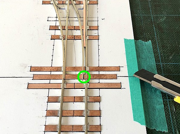
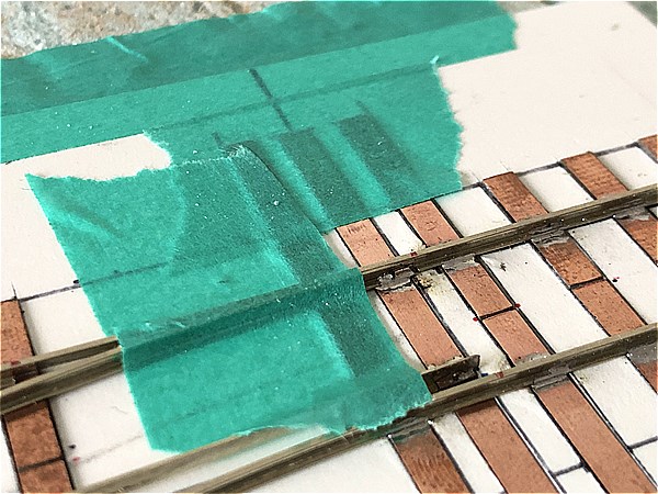
Use a triangle file to create electrical gaps with proper insulation. (Note: the area around the Switch Point Rail marked in green should be left for last.)
The gap positions are based on the same layout as PECO’s Electro Frog system.
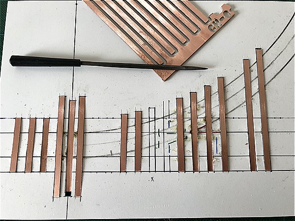
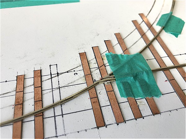
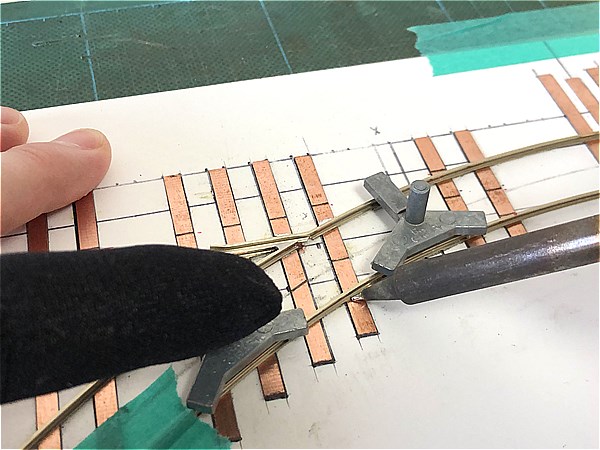
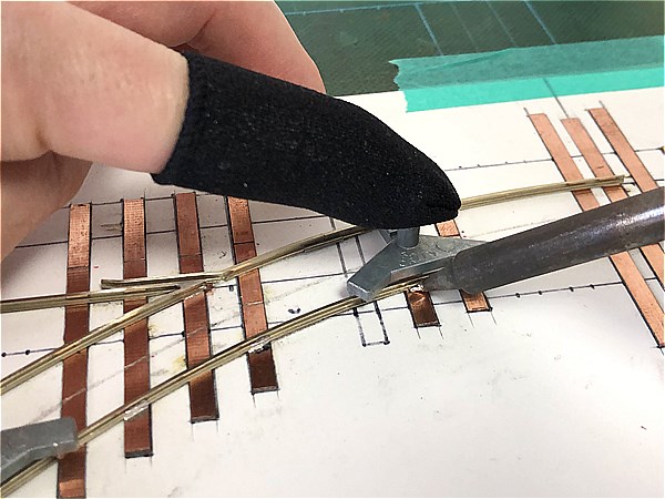
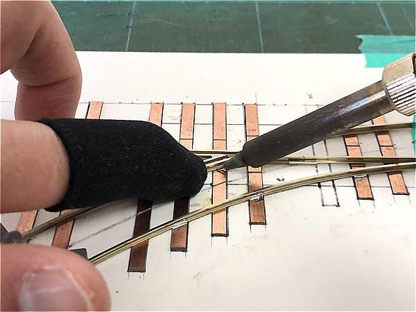
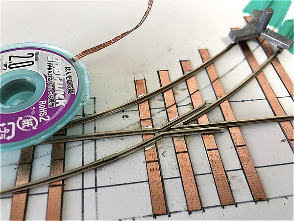
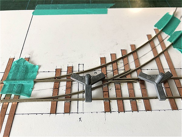
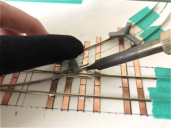
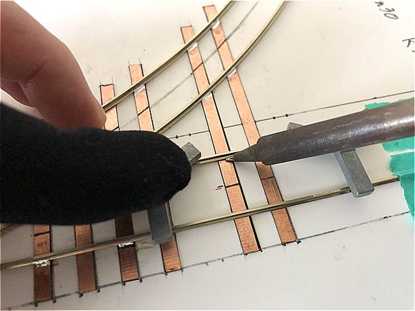
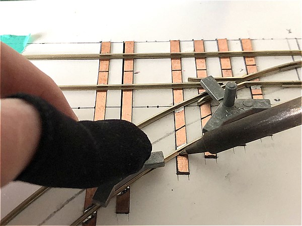
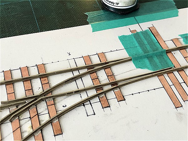
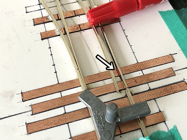
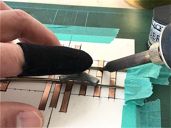
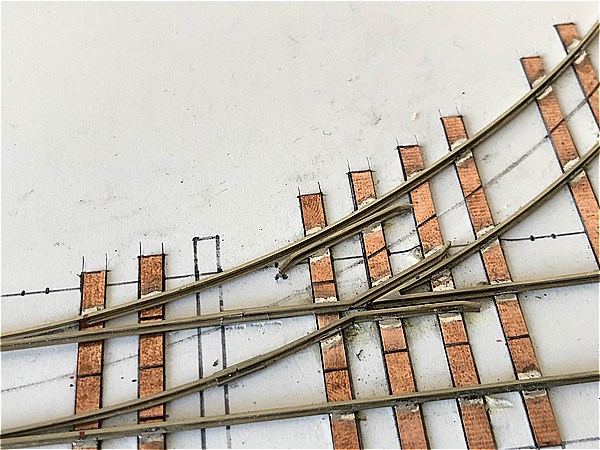
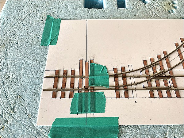
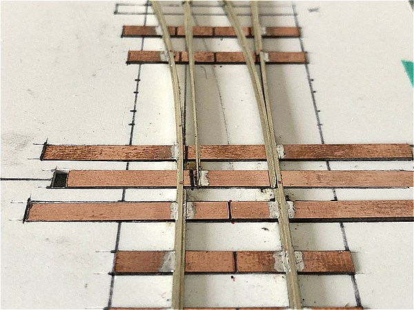
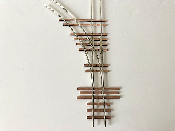
Curved Closure Rail + Wing Rail
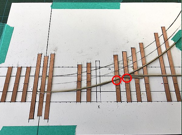
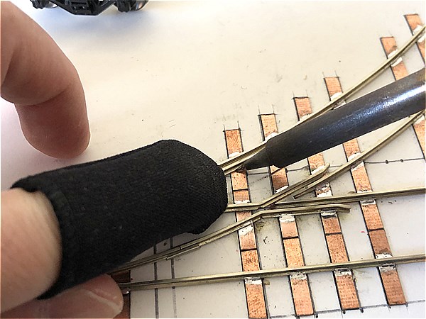
Align the track with the template drawing and secure it temporarily with masking tape to prevent any shifting.
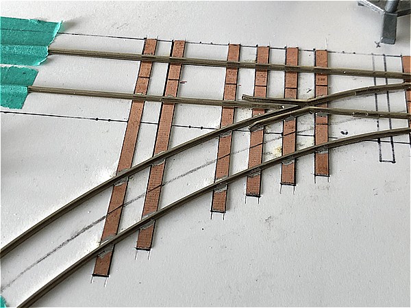
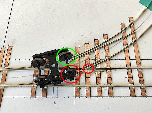
Check the flangeway and track alignment carefully!
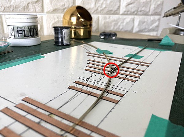
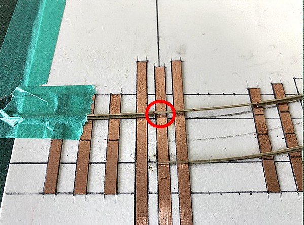
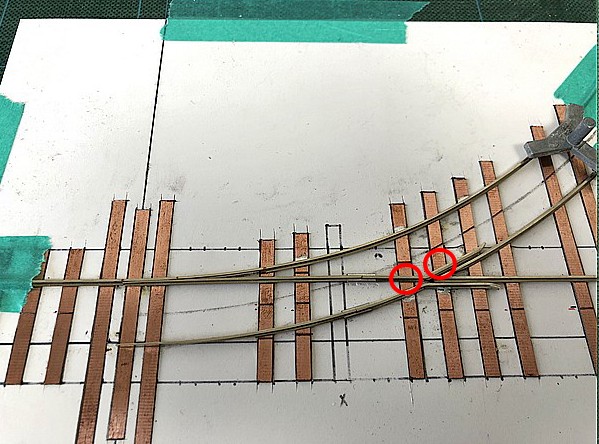
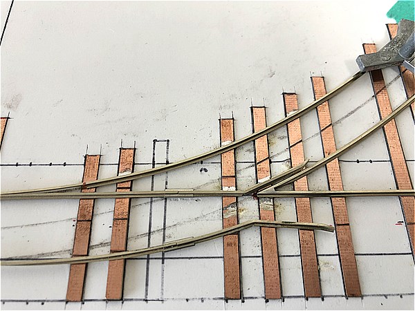
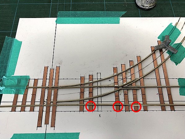
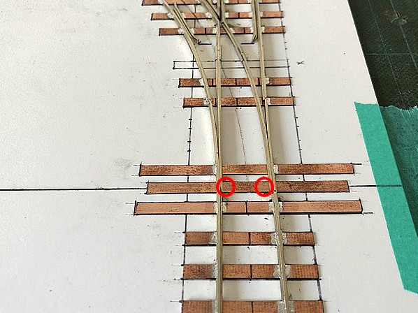
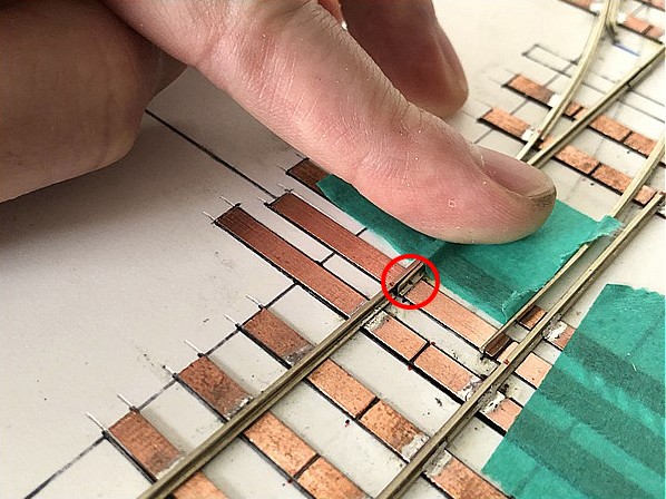
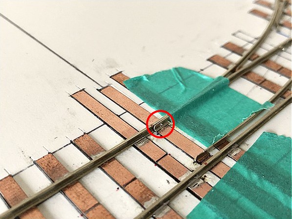
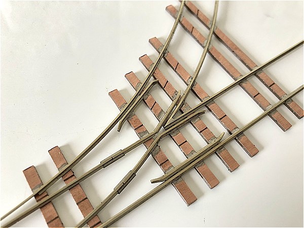
The frog is where multiple rails intersect — a complex and delicate area.
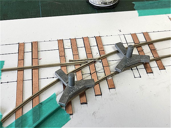
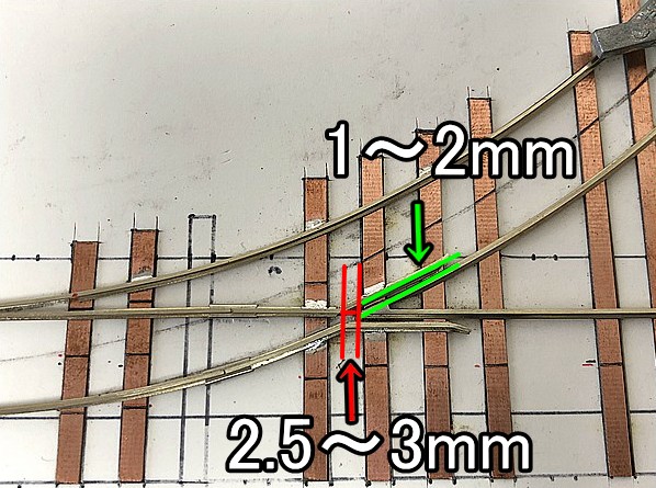
There are three critical points to check here:
- Crossing flangeway (1–2.0mm (0.079"))
- Gap between the Wing Rail point and Frog tip (approx. 2.5–3.0mm (0.118"))
→ If this gap is too wide, wheels may derail. - Alignment of Switch Point Rail → Frog → Frog Rail
→ Misalignment between the Frog tip and the Wing Rail corner (marked in red) can also cause derailments.
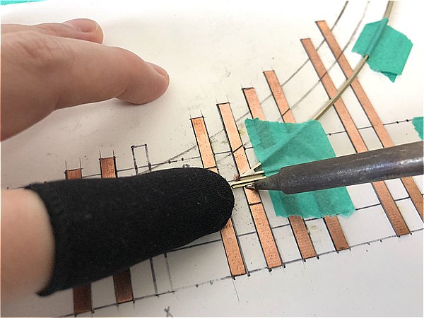
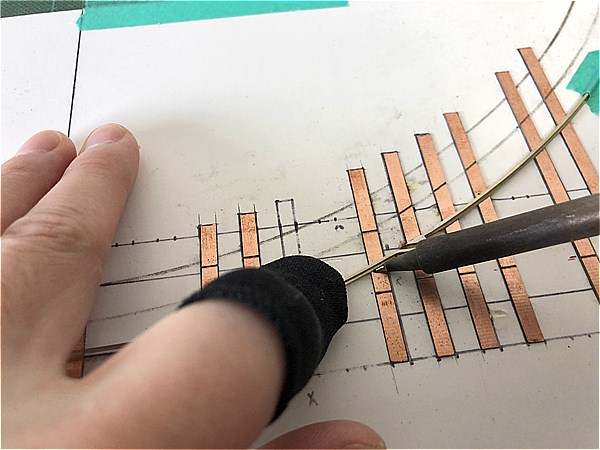
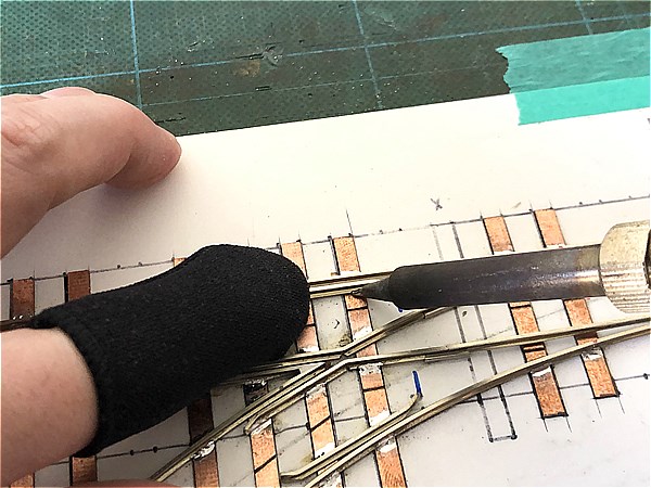
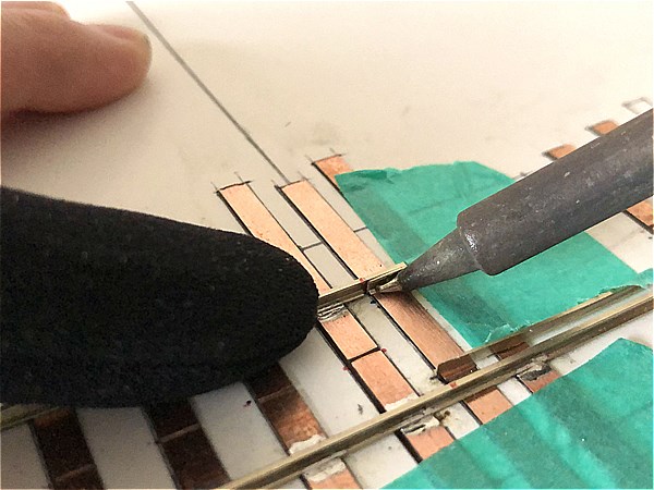
When soldering, take your time and follow the “Soldering Tips for a Clean Finish” carefully. Work one joint at a time with precision.
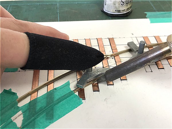
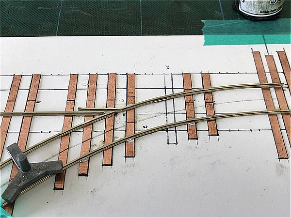
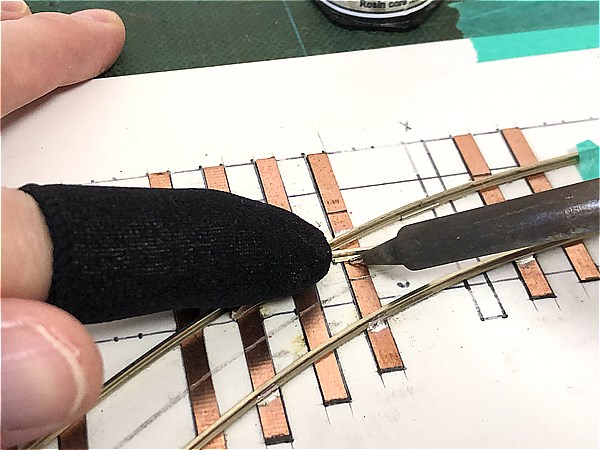
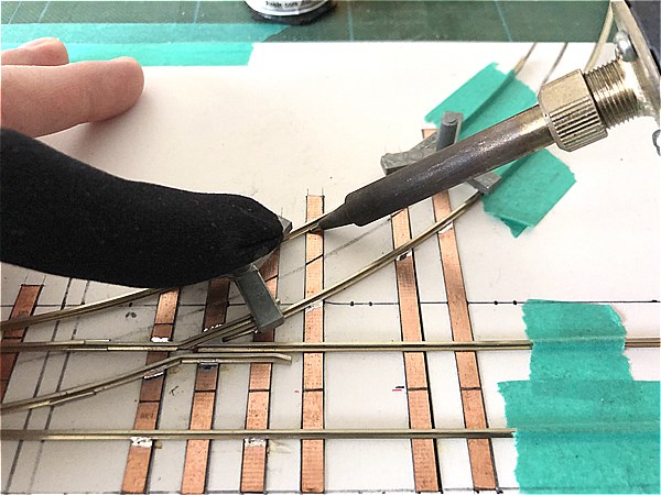
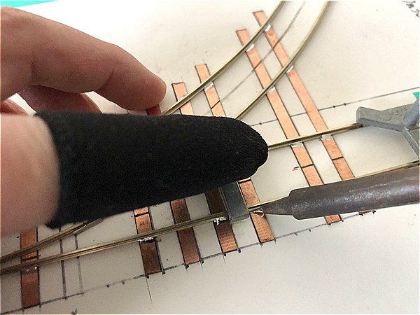
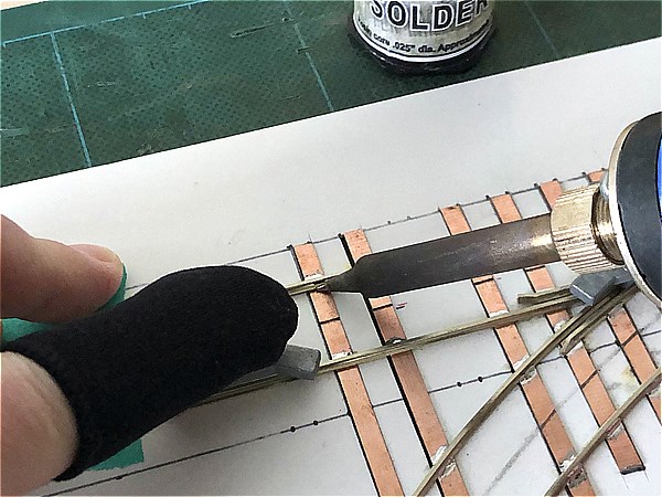
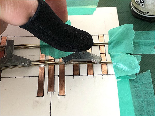
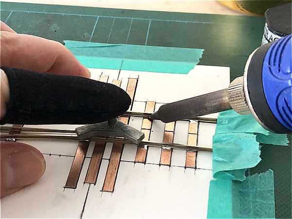
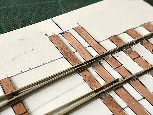
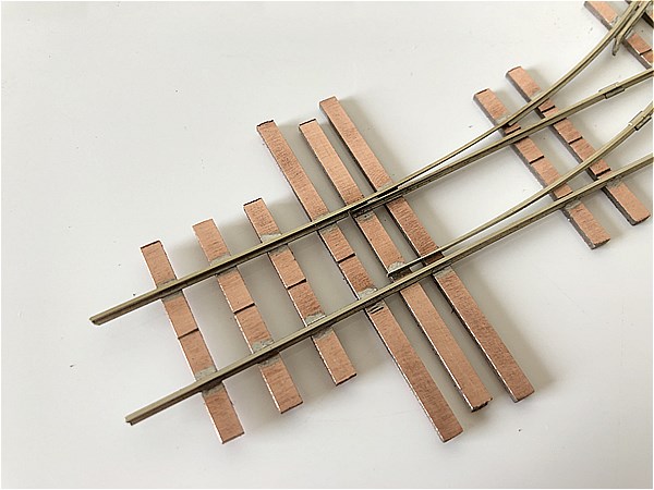
Stock Rail (Branch Line)
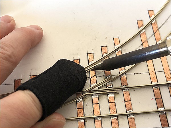
Next, solder the Stock Rail (Branch Line), which pairs with the Curved Closure Rail.
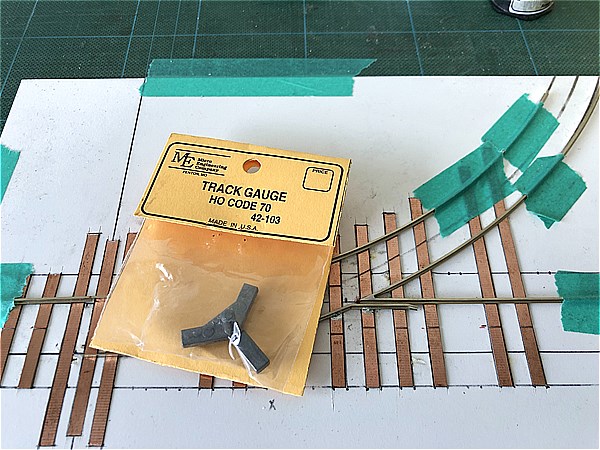
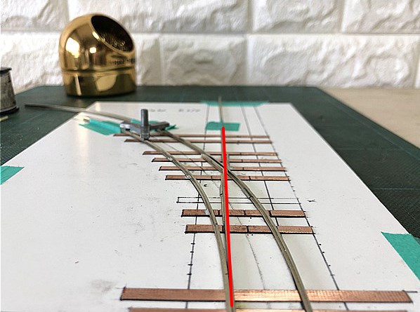
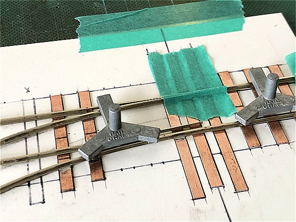
From this point onward, use a Track Gauge to confirm the rail spacing (gauge) as you go.
Start by soldering just a few key points to prevent shifting, rather than fixing the whole thing at once.
This is because full soldering too early can make future corrections more difficult if needed.
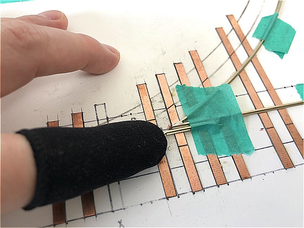
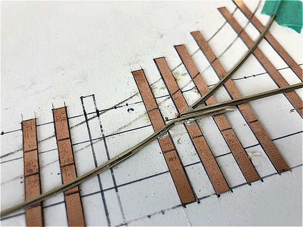
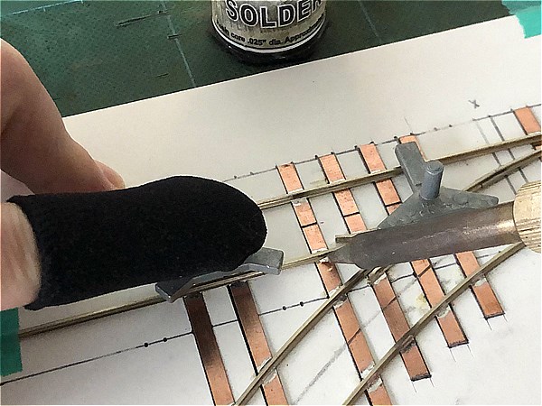
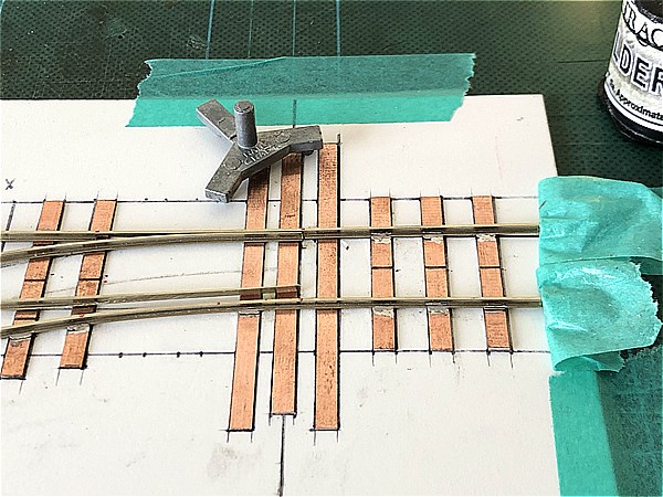
Check the fit between the Switch Point Rail and Stock Rail!
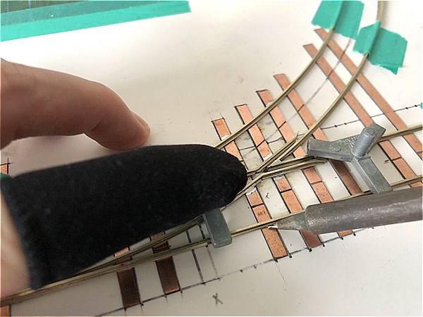
Before soldering, test-fit the Switch Point Rail (Tongue Rail), Closure Rail, and Wing Rail (Main Line) to confirm correct alignment with the Stock Rail.
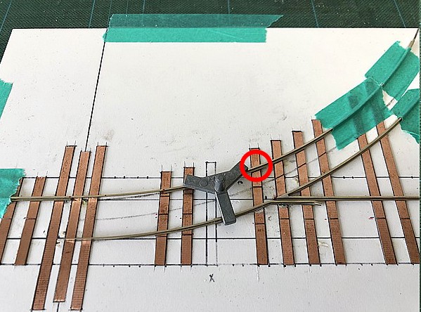
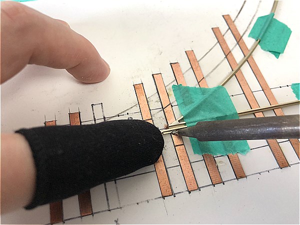
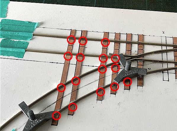
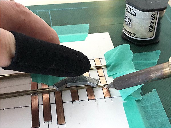
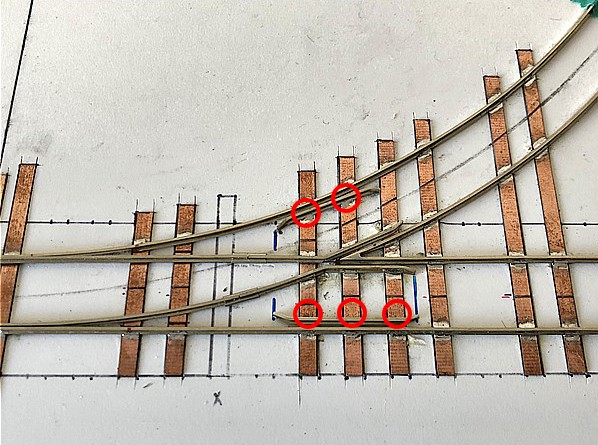
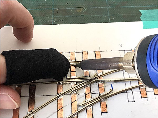
Begin soldering at the marked locations first.
This part is particularly critical, as it affects the vehicle’s transition through the frog (crossing).
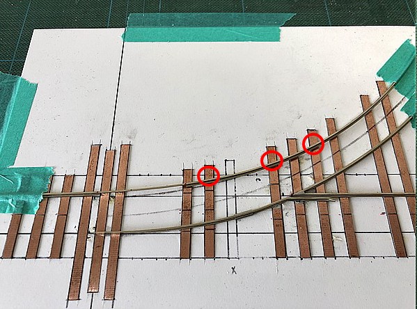
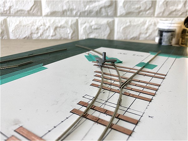
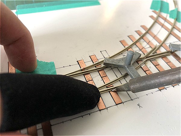
Use a Track Gauge to ensure the gauge is accurate as you solder.
One gauge is enough, but using two will help maintain consistent alignment and improve the overall accuracy of the turnout.
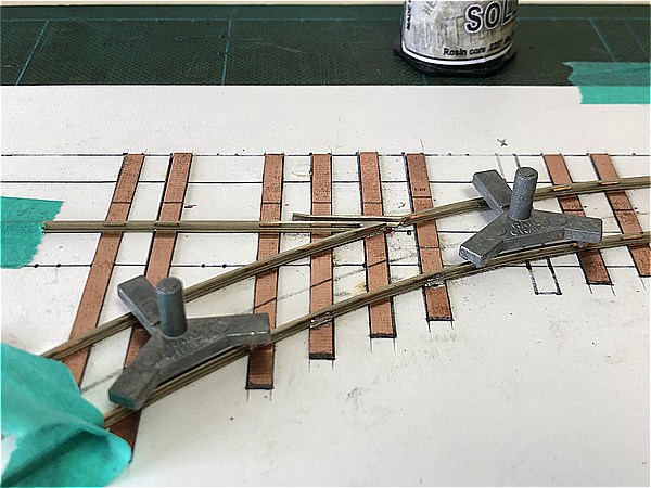
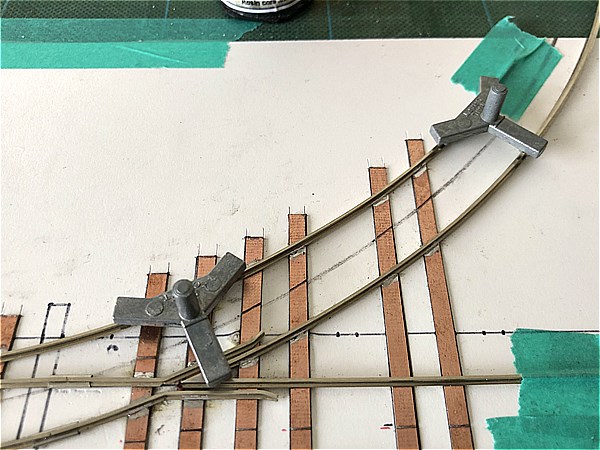
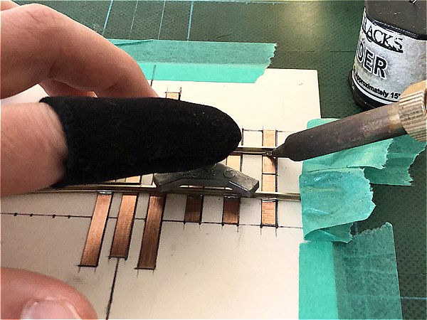
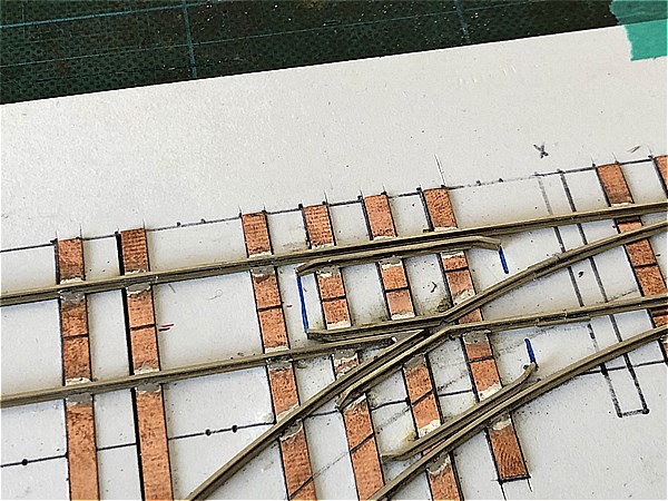
Move the Track Gauge as you go and solder the remaining two points.
This will complete the rail placement on the Branch Line side.
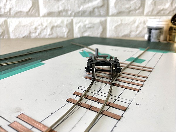
Visually check the alignment and use a bogie (truck) to ensure it won’t catch or derail at the frog.
Even if the vehicle shifts slightly to the Main Line side, don’t worry too much at this stage.
This can be corrected later by installing a Guard Rail (Check Rail).
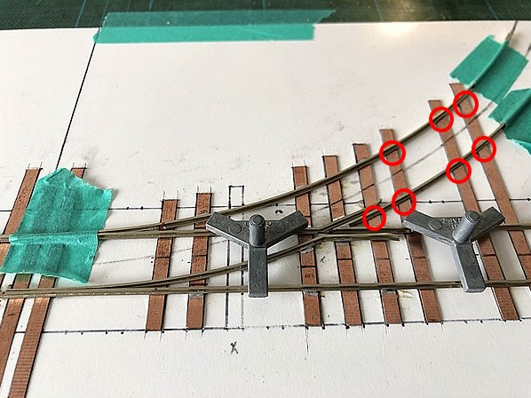
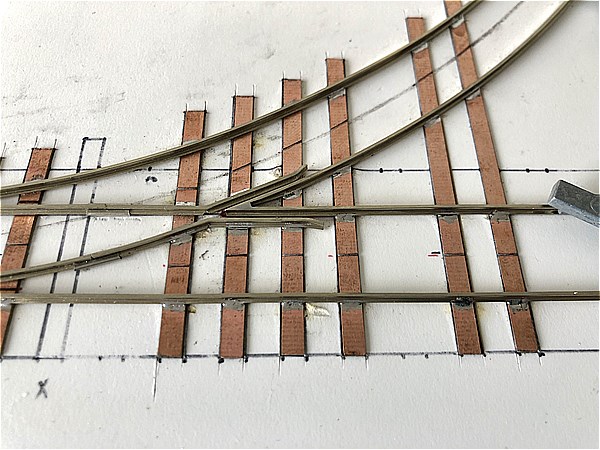
Straight Closure Rail + Wing Rail
Although we’ve already confirmed that the Switch Point Rail (Tongue Rail) fits the Stock Rail in the previous step, double-check before soldering this section.
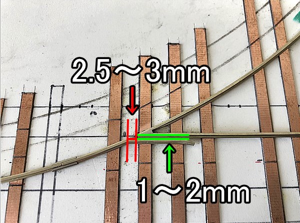
Be mindful of flangeway clearance and overall track alignment!
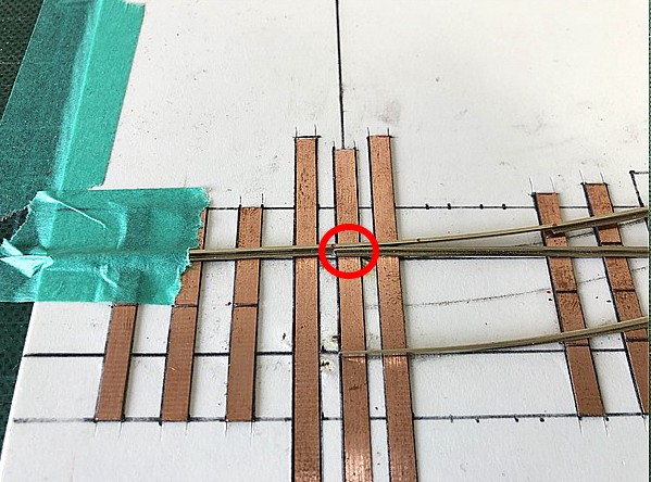
The key points are the same as with the “Curved Closure Rail + Wing Rail” step:
- Crossing flangeway spacing (1–2.0mm (0.079"))
- Distance between the tip of the frog and the corner of the Wing Rail (approx. 2.5–3.0mm (0.118"))
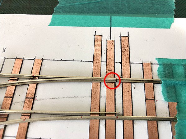
→ If this gap is too wide, it can cause derailments. - Ensure smooth alignment from the Switch Point Rail (Tongue Rail) through the Frog to the Frog Rail
→ Misalignment here (especially at the red-circled area) can also cause derailments.
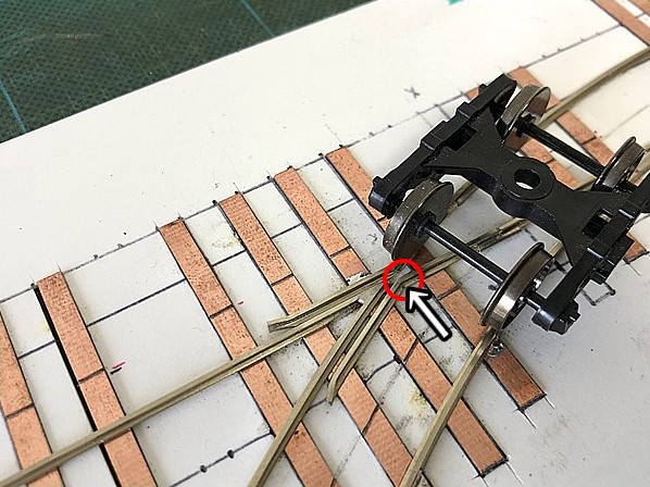
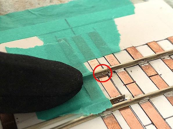
Pay special attention to whether the wheels will hit the corner of the Wing Rail (red circle).
Roll a bogie (truck) to visually test the clearance.
Although we mention numerical guides for flangeway spacing, always make final adjustments "by eye" using actual rolling stock.
In some cases, you may need to go back and slightly reposition the “Curved Closure Rail + Wing Rail” on the Branch Line side.
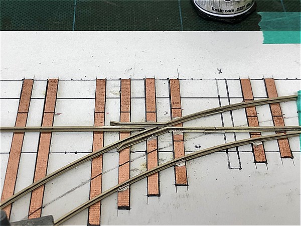
With both the Main Line and Branch Line’s “Switch Point Rail + Closure Rail + Wing Rail” properly fitted, we can proceed.
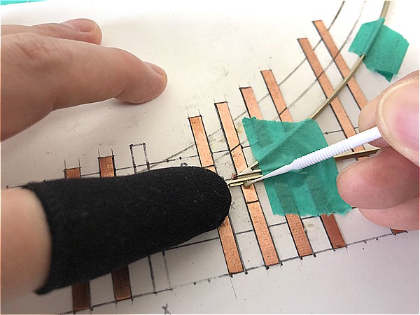
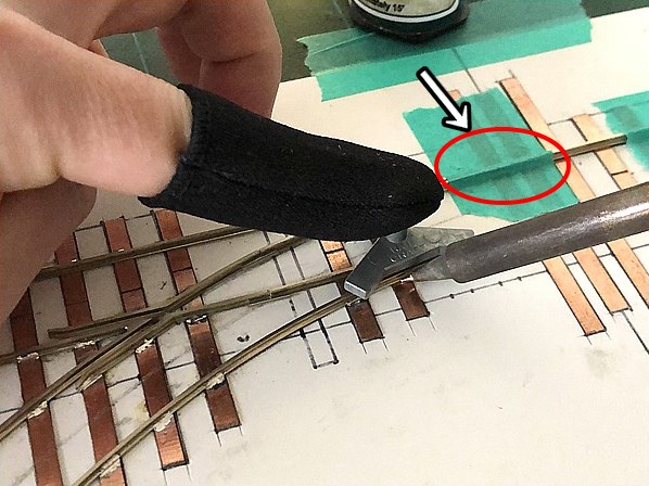
How to Fix Mistakes in Soldering
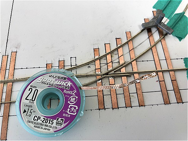
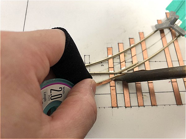
If you make a mistake, use solder wick (desoldering braid) to remove excess solder.
It’s very simple: place the wick over the solder and press with the tip of your soldering iron.
This technique is especially helpful during fine-tuning in the frog area.
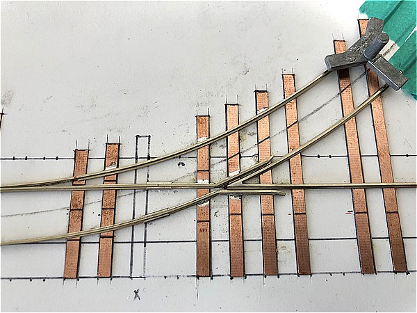
Stock Rail (Main Line)
Next, solder the Stock Rail for the Main Line side.
The key points are essentially the same as on the Branch Line side.
First, make sure that the Switch Point Rail (Tongue Rail) fits snugly against the Stock Rail.
Use a track gauge to verify spacing while tacking key positions with solder.
Carefully check that the wheels do not interfere with the frog or climb over it, ensuring there's no risk of derailment.
It’s possible that the Branch Line side may slightly guide the wheels toward the Main Line, but don't worry too much here.
This can be resolved later by installing a Guard Rail (Check Rail).
Frog Rail & Stock Rail (Branch Line)
This section is quite straightforward.
Simply solder carefully while checking the track gauge to maintain accurate spacing.
Frog Rail & Stock Rail (Main Line)
As with the previous step, solder gradually while shifting the track gauge along the rail to maintain proper alignment.
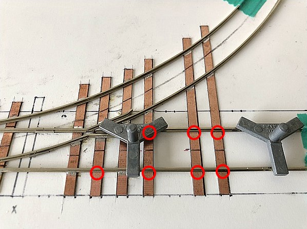
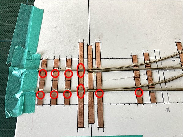
Finishing Around the Crossing
Since one side has already been soldered, you don’t have to be overly cautious.
However, the heat from the soldering iron can still cause other joints to melt, so always use a track gauge while working.
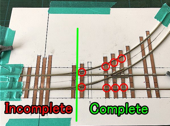
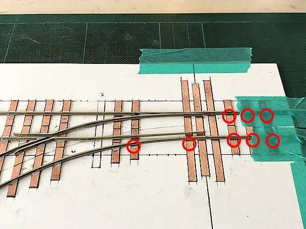
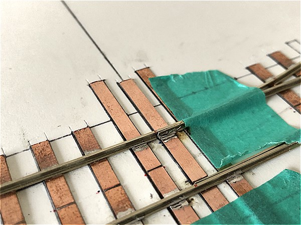
With the right half of the crossing completed, you can now proceed to the next step.
The marked areas are left unsoldered for now, due to the relationship between the Guard Rails (Check Rails) and the gaps.
Stock Rail (Around the Switch Point Rail)
We're now in the final stages of turnout construction.
Start by soldering the Stock Rail on the Branch Line side.
Important: Solder while the Switch Point Rail (Tongue Rail) is set toward the Branch Line side.
Firmly press the Switch Point Rail (Tongue Rail) against the Stock Rail to hold its position, and use a track gauge while soldering.
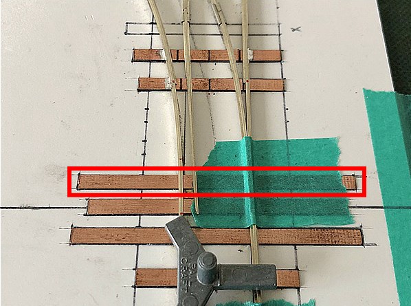
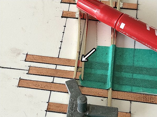
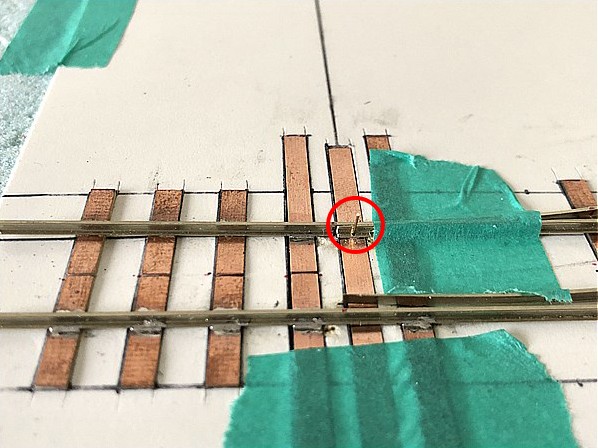
Cut gaps into the marked PC Board Turnout Ties.
To maintain proper gauge, cut the gap right next to the inside edge of the Switch Point Rail (Tongue Rail) while using the track gauge.
This step requires precision, so it's best to do it after securing the surrounding rails.
Finally, solder the remaining Stock Rail.
Finishing Stock Rail (Switch Point Rail Area)
At this stage, the track gauge should be stable enough, but continue using the track gauge while soldering just to be sure.
Cut a gap in the marked PC Board Turnout Tie.
This gap is easy to overlook, so take care not to forget it.
Guard Rail (Check Rail)
Installing Guard Rails (Check Rails) is especially important when working with tight-radius turnouts.
If you haven’t made the Guard Rails in the previous steps, now is the time.
Precise placement of Guard Rails is essential!
If you're experiencing any of the following:
- Trains don't smoothly enter the Branch Line
- Wheels hit the frog tip or derail
— most of the time, it's a Guard Rail placement issue.
When installing Guard Rails (Check Rails), pay attention to these two points:
- The Guard Rail should extend beyond the frog tip toward the Switch Point Rail
- The left front wheel should pass through the Guard Rail before the right front wheel reaches the frog
Once the placement is right, you'll also know the correct length.
Once installed, roll a bogie (truck) through to test the clearance and running performance.
If it rolls through this smoothly, you’re good to go.
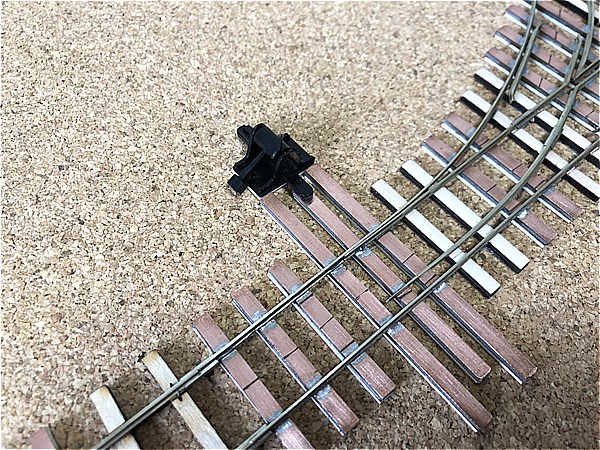
Switch Point Rail (Tongue Rail)
This is the final stage of the turnout build — the Switch Point Rail (Tongue Rail).
Begin by cutting a gap into the PC Board Turnout Tie.
This gap is extremely important and must be accurately placed.
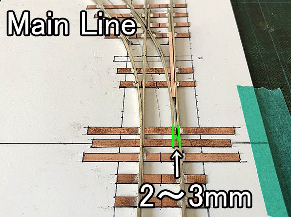
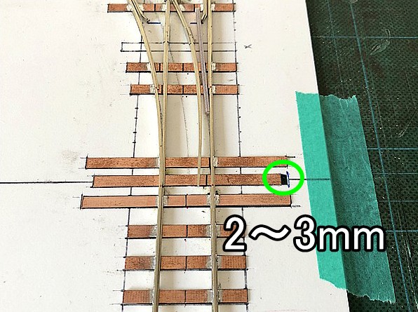
Start with the Main Line side.
Use a PC Board Tie as a spacer (2–3.0mm (0.118")) to mark the outer limit of the Switch Point Rail (Tongue Rail).
Next, trim the template (jig) by 2–3.0mm (0.118") to match.
This becomes the clearance area for the tongue rail's movement.
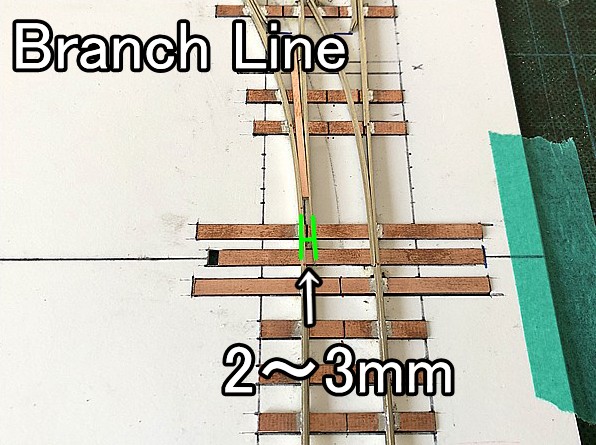
Repeat the same steps for the Branch Line side.
Remove the turnout from the jig and cut the gap.
Use a bogie truck to check functionality!
Rolling stock tends to shift outward due to centrifugal force.
If a wheel so much as touches the Switch Point Rail (Tongue Rail) on the Main Line side, it can cause a short circuit.
Be sure to roll a bogie truck through to confirm.
Before soldering, insert a reinforcement rod (brass wire) into the Switch Point Rail (Tongue Rail).
This is crucial because the tighter the radius, the greater the stress on the tongue rail.
Although solder can weaken over time, reinforcement improves durability.
This method is our original solution, developed through trial and error.
*Tip: Placing Styrofoam under the jig makes this process easier.
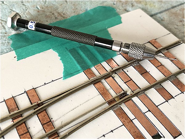
1. Drill a hole in the Switch Point Rail (Tongue Rail)
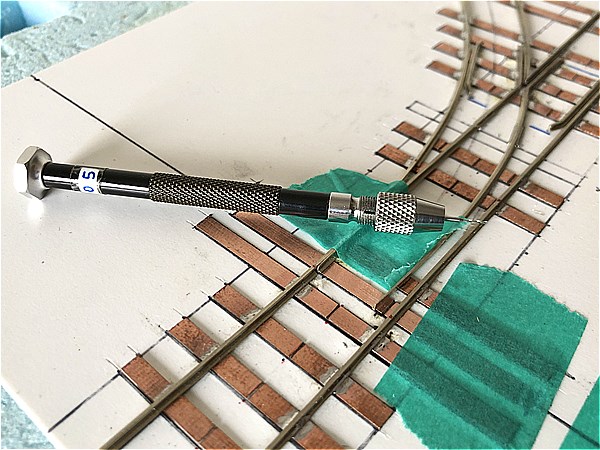
Using a pin vise (0.4–0.5mm (0.020")), drill a hole at the inner corner of the tongue rail.
Be careful not to damage the base of the rail.
Note: While this example shows unsoldered rails for clarity, pre-soldering adds strength.
2. Insert the brass rod
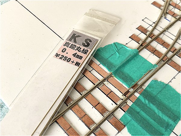
Insert a brass rod (0.4mm (0.016") or 0.5mm (0.020")) as a post and push it to the appropriate depth. With Styrofoam below, this should be easy.
Ensure that the rod does not interfere with wheel movement.
3. Solder to secure the rod
Solder the brass rod in place. Since this area experiences the most stress, applying extra solder is acceptable.
4. Cut the excess rod
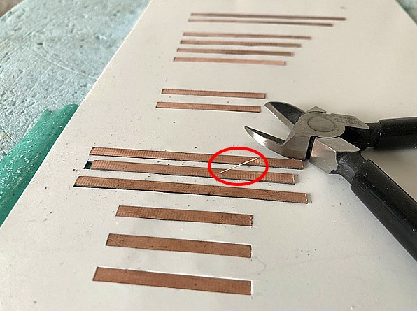
Cut the excess rod on the underside and file it flat to finish the reinforcement.
Repeat the same reinforcement for the Branch Line side.
Use the brass rod as a post to fix the Switch Point Rail (Tongue Rail) and PC Board Tie together.
This strengthens the connection, which otherwise could be weak due to soldering on only one side.
Leaving the rod’s head slightly exposed helps maintain structural integrity even if the solder weakens over time—like a pin lock.
After confirming the movement of the tongue rail, soldering is complete!
Check Power & Running
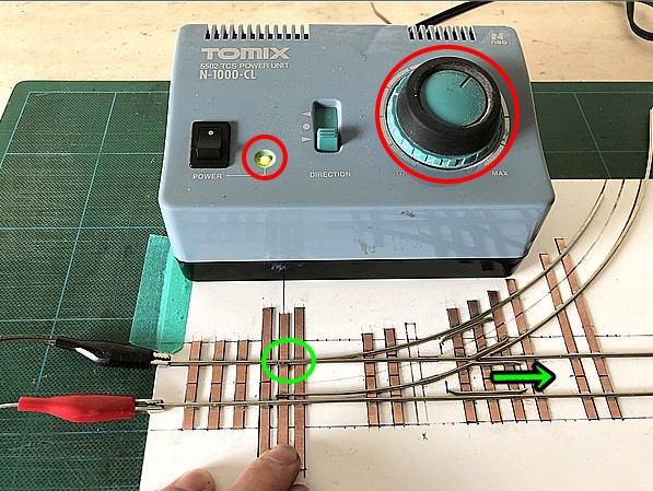
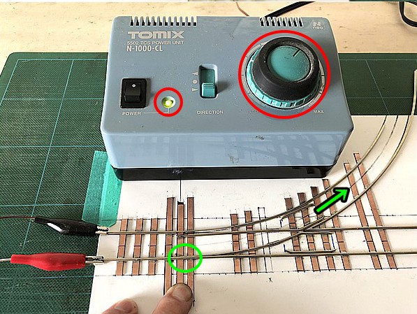
Once all soldering is complete, check electrical continuity and perform a running test using a powered vehicle.
It's better to do this before installing it into your layout to avoid surprises.
First, check for shorts or electrical issues.
Toggle the Switch Point Rail (Tongue Rail) between the Main Line and Branch Line. If the power pack’s lamp stays green, you're good.
If the lamp turns red, there's likely a short circuit due to a missing gap.

If there are no electrical problems, test with an actual powered vehicle.
Always verify smooth operation before embedding it into your layout.
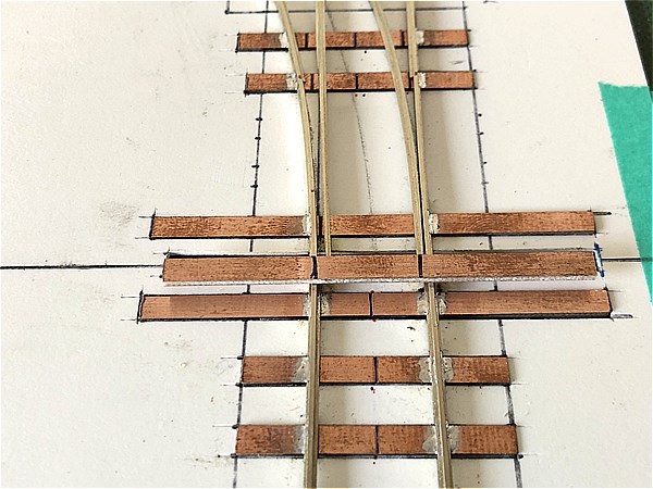
Cleaning Solder and PC Board Ties
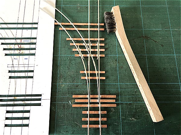
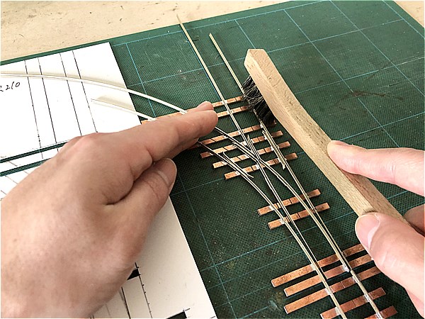
Finally, clean the solder joints and PC Board Ties using a wire brush.
Hold the brush at a slight angle for better results.
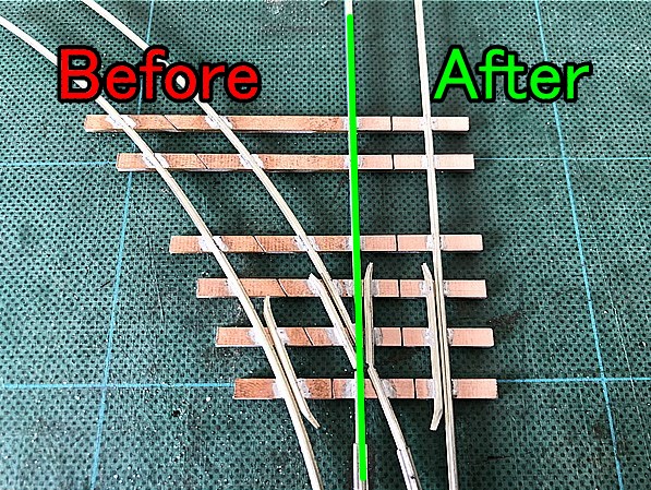
As seen in the comparison, cleaning dramatically improves the appearance.
This step is small but essential for a professional finish.
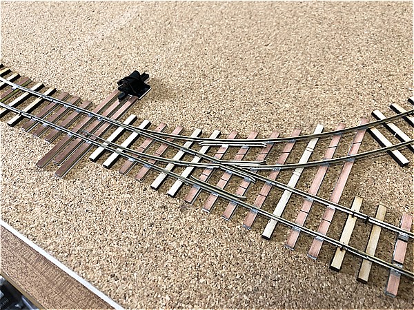
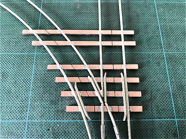
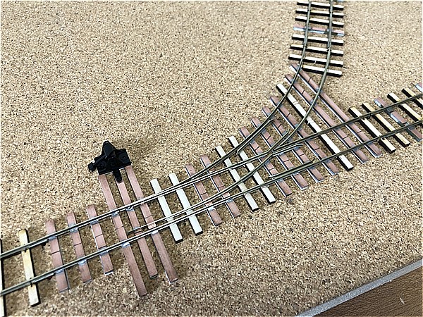
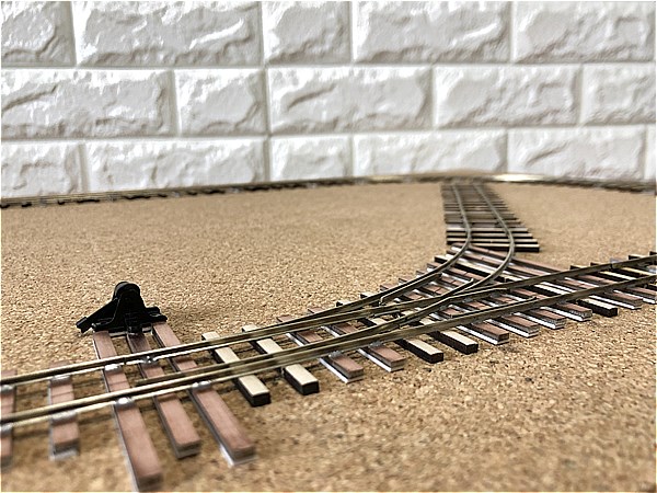
Original Self-made Turnout Completed!
After trimming the excess rail, the turnout is complete!
You can glue the wood ties when installing it into your layout.
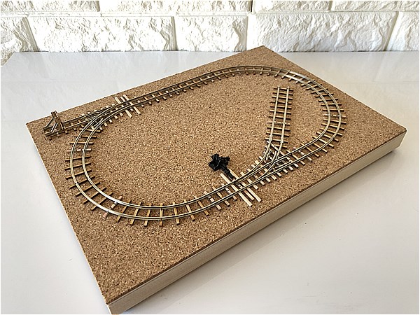
Installing the Self-made Turnout into a Layout
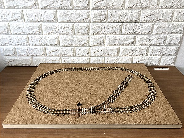
This is the self-made turnout installed into a B2-sized (728.0mm (28.661") x 515.0mm (20.276")) layout.
Adding wood ties gives it an even more realistic feel.
Power Routing Method of the Self-made Turnout
Same method as PECO Electro Frog Turnouts
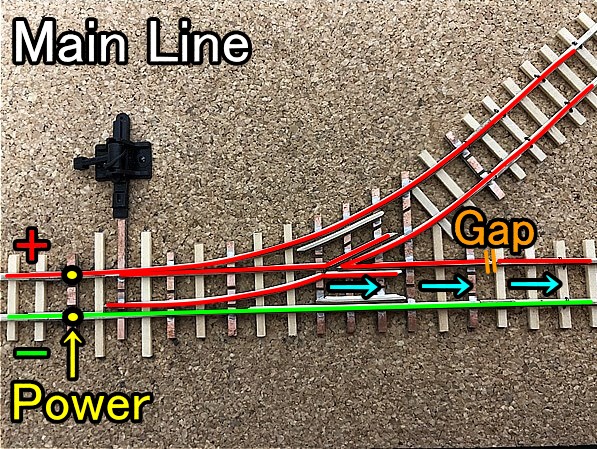
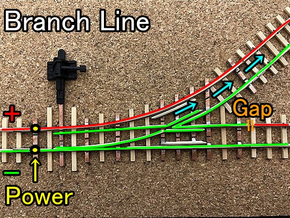
The power routing is the same as PECO's "Electro Frog Turnouts."
The non-selected route is electrically the same polarity as the selected one.
Contact us
Please feel free to send us your requests and work requests via our contact form.!!
Narrow Gauge Shop
Satoru Mimura
1-15-27,Negishi,Machida,
Tokyo,JAPAN 194-0038
E-mail narrow_gauge_shop@ae.auone-net.jp
https://www.youtube.com/c/narrowgaugeshop
https://www.pinterest.jp/narrowgaugeshop/_created/
We're very active on YouTube and Pinterest, so we'd love it if you'd subscribe to our channel (follow us) and hit the good button.
-
How to make HOe Micro Layout Baseboard with Self-made Turnout by Narrow Gauge Shop